Active Aero Wing (AAW)
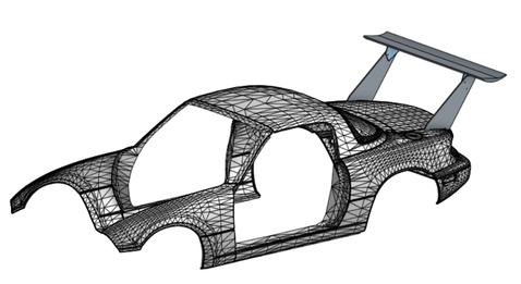
The active aero wing project was inspired after turbocharging my 1997 Mazda Miata. The wing serves as a means of increasing tire traction as well as braking capabilities. Extensive CAD design in OnShape and FEA in Abaqus was conducted to balance structural rigidity and performance characteristics. The wing and wing mount were purchased from 9LivesRacing and the base plate as well as the active elements were designed by myself.
The base plate was designed with multiple fluid and mechanical constraints. First, the base plate was designed to be tall enough as to extend the wing above the top of the vehicle. This was done to ensure the wing experiences more predictable free stream air as opposed to the unpredictable wake produced by the aerodynamics of the vehicle. Second, the mounting location was designed to sit as far back along the trunk as possible. This was done to have have half of the wing sit behind the top of the trunk to prevent pressure buildup on the suction side of the wing as well as decrease the moment on the bolts holding the base plate to the trunk. The analysis seen below uses Aluminum 6061 as the base plate materials. This material was selected due to it's lower cost and weight as well as it's high yield strength.
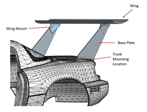
Figure 1.1: AAW Assembly
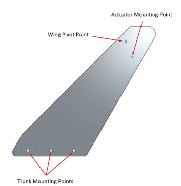
Figure 1.2: Base Plate Design
MATLAB Work
Linear actuators were used to drive the wing assembly forward and back. To determine the load the actuators required to drive the wing, a MATLAB script was created. The script calculated downforce using the wing dimensions, and plots were created to determine the load on the wing at varying angles of attacks and vehicle speeds.
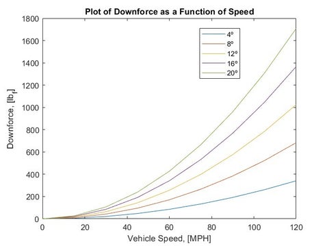
Figure 1.3: MATLAB Plot of Downforce as a Function of Speed
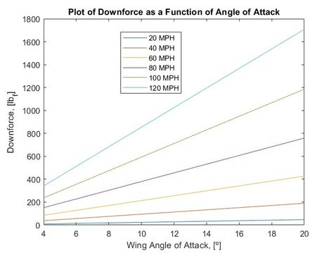
Figure 1.4: MATLAB Plot of Downforce as a Function of Wing Angle of Attack
The active aero wing features two linear actuators (one on each base plate). Since the maximum load on the wing was 1700 lbf at a speed of 120 MPH and an angle of attack of 20 degrees, each actuator must be capable of handling at least 750 lbf. *Actuator has not yet been determined*
FEA WORK
Abaqus was used to determine the structural integrity of the base plate as well as adjust the design and material to optimize weight and cost. *Note: Hole locations and sizes on the base plate were not yet determined at the time of FEA analysis*. Loading and boundary conditions applied to the model can be seen in Figure 1.4. The bottom of the base plate (at the hole locations attached to the sidewall of the trunk) was modeled to be fully fixed meaning it has zero degrees of freedom. The force was applied as a pressure force on the top surface of the wing and was calculated by dividing the maximum force (1700 lbf) by the surface area of the wing (chord*width).
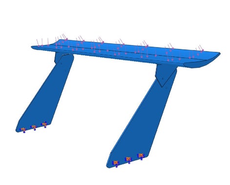
Figure 1.4: Loading conditions on AAW Assembly
Next, the mesh was developed and convergence of the model as well as the aspect ratios of the elements were checked and modified by adjusting the seed size to ensure accurate results. Quadratic tetrahedral elements were used over linear tetrahedral elements to ensure the most accurate results. For a model this small, quadratic elements did not significantly increase simulation time.
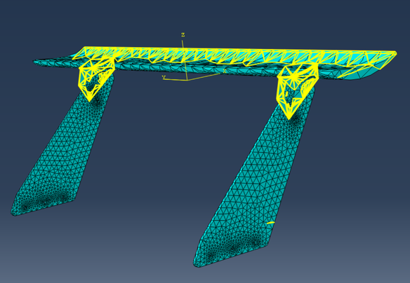
Figure 1.5: Highlighted Elements with Aspect Ratios Greater than Five
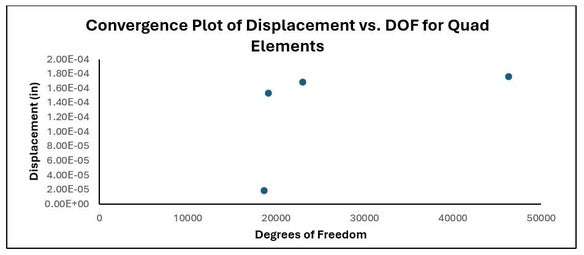
Figure 1.6: Convergence Check, Plot of Maximum Displacement vs Total Degrees of Freedom
The results of the simulation yielded a maximum von Mises stress of 26,876 PSI and a maximum deflection of 8.1E-6 inches. This resulted in a factor of safety (FOS) of around 1.3. This is a sufficient FOS as the vehicle will rarely reach 120 MPH. The maximum stress was located at the hole locations for the pivot point and actuators. Further analysis will need to be conducted as the hole diameters will increase (resulting in increased stress concentrations) to fit hardware.
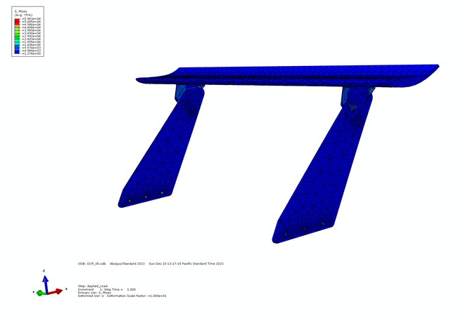
Figure 1.7: Stress Contour Plot of AAW Assembly
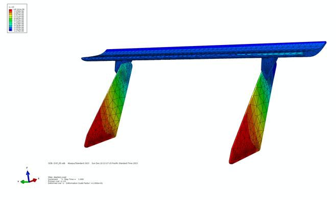
Figure 1.7: Displacement Contour Plot of AAW Assembly
Refining Design Work
*Linear actuator selection is still being worked on*
The pivot mechanism consists of press fit brass bushings, steel shoulder screws, Teflon washers, locking nuts, and single wave washers.
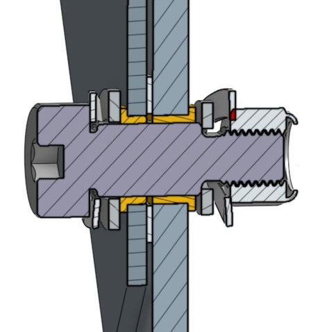
Steel shoulder screws were implemented due to their high yield strength, and the press-fit brass bushings were implemented due to their low coefficient of friction with steel. A bushing/ shoulder screw approach was taken in order to separate the experienced loads in a dynamic setting. The bushing experiences rotational loads mainly due to friction, and the shoulder screw experiences the shear loads. The low coefficient of friction between steel and brass allows the assembly to pivot with minimal resistance.
Teflon washers were placed at each point of contact to reduce friction and single wave washers were used to fine-tune the clamping force between the bolt and the lock washer.