Pinzgauer EV Conversion
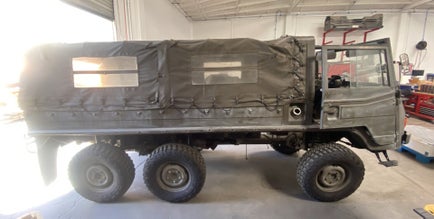
The electric conversion of the Pinzgauer was a project I was working at during my three month internship at Trajectory EV a startup based in Salinas, California. I was given the opportunity to manufacture an implement the battery pack that will be used in the vehicle, as well as design a few components along the way.
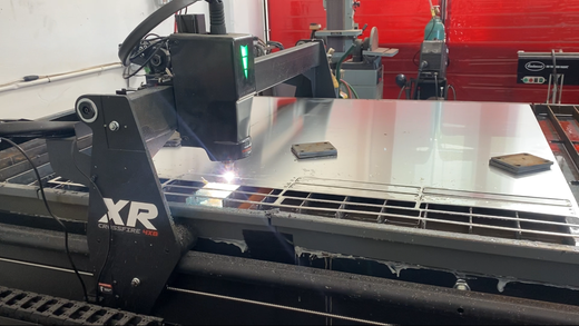
To start, the pack was designed to have 16 modules in series with 8s LiFePo4 cells per module. The total pack voltage was 440V. The cells were first setup to be passively balanced. While the cells were balancing, manufacturing of the module casings were undergo. The module straps were manufactured from a 5 series aluminum alloy and cut on a plasma cutter. This aluminum was chosen due to availability and avoidance of the more conductive 2 series aluminum. The top and bottom plates were made of sheet aluminum that were bent and welded. Each module casing had a foam lining placed on the inside to prevent a possible short.
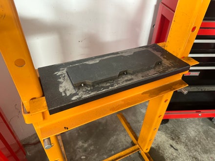
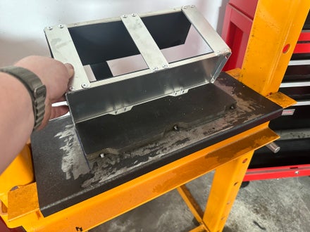
Once assembly of the casings were complete and the cells were done balancing (all cells had around the same voltage), each cell was wrapped in Kapton tape to prevent a short and the modules were ready to be assembled. Previously, the modules were pressed on a manual hydraulic press machine with no fixture. To decrease the lead time of assembly, I designed a fixture in OnShape to fit the contours of the hydraulic press and module casing. The fixture was made of 3/8" steel and was manufactured using a waterjet at the local machine shop. The size and material were selected based on availability of material at machine shop and to prevent deformation when pressing.
Once the modules were assembled, they were laid out in the orientation that they would be placed in the vehicle. The pack was split into two half-packs in order to fit in the two side compartment areas that were designed for the vehicle. After the modules were placed in their respective locations, a wiring harness consisting of cell tap wires for the BMS were made and placed. After the cell tap harness was made, jumper cables were manufactured using copper ring terminals and 0 gage wire. The jumper cables and bus bars were placed to connect the pack in series.
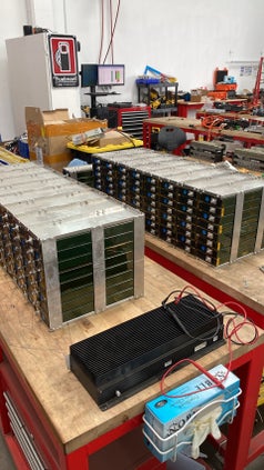
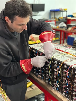
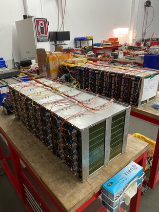
The cell tap connections were checked using a cell tap validation tool, and the pack began actively balancing with no issues upon first connection to the BMS.
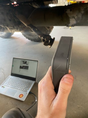
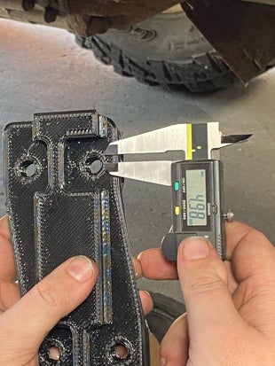
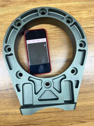
Once the pack was completed, design of the motor mounts were started. The undercarriage of the vehicle was 3D scanned and placed into an OnShape assembly to assist with the design. Then, a rapid prototype of the motor mounting hole to the axle case was 3D printed and checked. The holes were slightly off and had to be remeasured and designed.
Sadly I couldn't see the project through as I had to go back to school to finish my last year at Cal Poly.